Mini-workshop “Motores de Passo”

(scroll down for English)
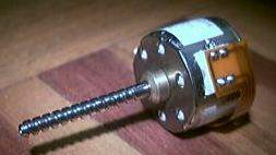
Vamos pegar ale­a­tó­ri­a­men­te num motor de pas­so e ten­tar des­co­brir que tipo de motor é, dese­nhar um dia­gra­ma sim­ples do mesmo.
Depois vamos pegar no fer­ro de sol­dar (não há que ter mee­e­e­e­e­do :)) e mon­tar um cir­cui­to que per­mi­te con­tro­lar esse motor a par­tir de um Ardui­no ou qual­quer outra pla­ca base­a­da num microcontrolador.
Todo o mate­ri­al é for­ne­ci­do e fica para os par­ti­ci­pan­tes, sen­do ape­nas neces­sá­rio tra­zer fer­ro de sol­dar e mul­ti­me­tro (ou espe­rar que algu­ma alma cari­do­sa vos empreste).

O núme­ro de par­ti­ci­pan­tes é limi­ta­do pelo que, se dis­se­rem que vêm, con­ta­mos MEEESMO convosco 😉

Para ins­cri­ções e pedi­dos de infor­ma­ção: workshops /arroba/ audienciazero.org
Lota­ção máxi­ma de 10 participantes
Sába­do 13 de Mar­ço de 2010
AltLab em Cacilhas
14h00m
5€


Let’s each of us pick up a ran­dom step­per and try to find out what kind of step­per it is, draw a sim­ple diagram.
Then pick up the sol­de­ring iron (have noo­o­o­oo fear :)) and assem­ble a cir­cuit to con­trol that motor from an Ardui­no or any other micro­con­trol­ler-based board.
All mate­ri­als are sup­pli­ed to the par­ti­ci­pants and everyo­ne gets to keep them; you’­re just requi­red to bring your own sol­de­ring iron and mul­ti­me­ter (or wait a ran­dom amount of time to bor­row some­o­ne else’s).

The num­ber of par­ti­ci­pa­ti­ons is limi­ted, the­re­fo­re, if you tell us you’ll come, we’ll REEEALLY be wai­ting for you 😉

For regis­tra­ti­on and infor­ma­ti­on requests: workshops /at/ audienciazero.org
Maxi­mum of 10 participants
Satur­day, Mar­ch 13 2010
AltLab @ Cacilhas
14h00m
5€
Drum Pads

drumpads1drumpads2

Hey.

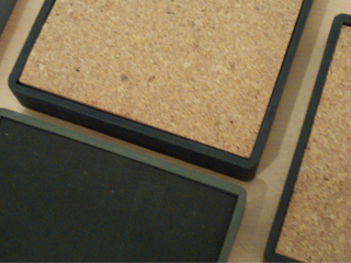
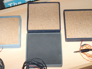
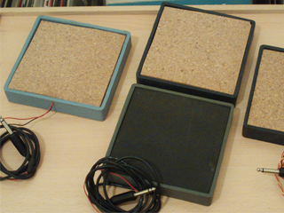
Four drum pads ready to go.

All made of old mate­ri­al found in the Alt/Lab ins­tal­la­ti­ons, and a very spe­ci­al big thankxxx for Móni­ca who brought the casings (we are going back to that in a moment) for the drum pads.

So the idea was to make drum pads that we could hook up to a sound card(or wha­te­ver) and them make swe­et music, this is a very nice com­bi­na­ti­on betwe­en pie­zo­e­lec­tric com­po­nents and a few layers of some absor­bent sound  mate­ri­al like rub­ber or cork foil (that’s what we use becau­se the­re was nothing more) and a pie­ce of alu­mi­num foil for a gre­a­ter drum area .

We use an old can (20l) of paint, four pie­zo­e­lec­tric found in elec­tro­nic junk like old modems and old telepho­nes, wire for con­nec­ting the pie­zos, cork foil for insu­la­ti­on the drum pad area and Móni­ca sup­ply the casings (squa­re rub­ber cd´s stands), and glue for put­ting everything nice and tight .

First we cut a pie­ce of the can (cir­cu­lar about 10cm radius)and we glu­ed the pie­zo into it, then we dril­led one hole into the rub­ber casing for the wires to came out, them we cut two squa­re cork foil parts (the first in the bot­tom of the casing and the other for the top) a bit of glue and that’s it drum pads ready to rock.

Now we got some audio coming out of the pads but thats just boring becau­se its always the same and we want to go further like trans­for­ming audio into midi mes­sa­ges, and we found the right tool for it, its cal­led  “KTDrum­Trig­ger” and he trans­forms the audio sig­nal into midi notes, we can use this midi notes insi­de a sequen­cer pro­gram to con­trol any kind of ins­tru­ment (either VSTI or some other stuff), in our case we use the drum pads to con­trol “Bat­tery” and thats it ins­tant fun.

The­re are some other links and some other ide­as for drum pads. This “one“uses ardu­nio as a sour­ce for the imput signal.

drumpads3

PAPERduino’s design

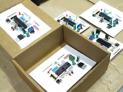
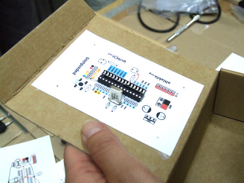
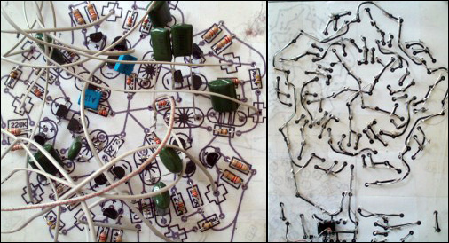
This is a fully func­ti­o­nal ver­si­on of the Ardui­no. We eli­mi­na­ted the PCB and use paper and card­bo­ard as sup­port and the result is.. the PAPERduino 😀

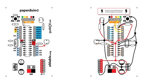
This is the the first ver­si­on of the layout design, next we will try more designs, and other mate­ri­als. You just need to print the top and the bot­tom layouts, and glue them to any kind of sup­port you want. We hope that you start making your own boards. If you do, ple­a­se sha­re your pho­tos with us, we would love to see them 😉

The­re is no USB direct con­nec­ti­on, so to pro­gram the paper­dui­no you will need some kind of FTDI cable or adap­ter. One of this pro­ducts will be fine:
FTDI cable from Ada­fruit Industries
FTDI adap­ter from Sparkfun

Down­lo­ad PDF

Com­po­nents list:
1 x 7805 Vol­ta­ge regulator
2 x LEDs (dif­fe­rent colors)
2 x 560 Ohm resis­tors (betwe­en 220oHm and 1K)
1 x 10k Ohm resistor
2 x 100 uF capacitors
1x 16 MHz clock crystal
2 x 22 pF capacitors
1 x 0.01 uF capacitor
1 x button
1 x Atmel ATMega168
1 x soc­ket 28 pin
Fema­le and Male headers

Ins­truc­ti­ons:
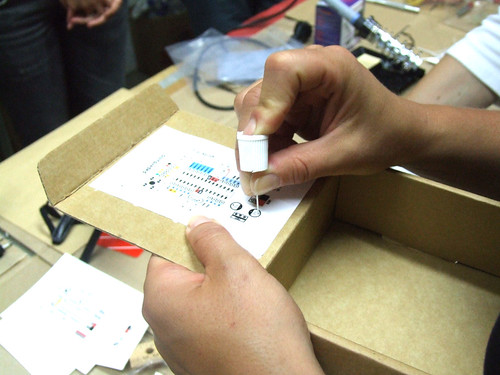
Use a nee­dle to punc­tu­re the holes for your components.

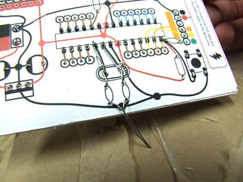
Don’t rush, pla­ce one com­po­nent after another and do all the sol­der work carefully.

Fol­low the con­nec­ti­on lines.

And this should be the final look of your paper­dui­no connections.

openMaterials :: research project

openMaterials
My dear fri­end Kisty Boy­le and I recen­tly laun­ched open­Ma­te­ri­als — a col­la­bo­ra­ti­ve rese­ar­ch pro­ject dedi­ca­ted to open inves­ti­ga­ti­on and expe­ri­men­ta­ti­on with DIY pro­duc­ti­on methods and uses of mate­ri­als. In the spi­rit of the open sour­ce soft­ware and hard­ware move­ments, we hope to pro­mo­te mate­ri­als to be rese­ar­ched and deve­lo­ped in a public, col­la­bo­ra­ti­ve man­ner. We see mate­ri­als as an open resour­ce, and wish to esta­blish an open pro­cess for explo­ring and sha­ring kno­wled­ge, tech­ni­ques and appli­ca­ti­ons rela­ted to mate­ri­als science.

I’ll be con­duc­ting most of my hands-on rese­ar­ch right here at AltLab. We’d love for you to be invol­ved if you are wor­king in the­se are­as or inte­res­ted in lear­ning more about smart materials.

Paper and cardboard circuits

papercircuits_01
A cou­ple of years ago i found out on the “inter­nets” that you don’t really need a pro­to­bo­ard or a cir­cuit board to make your cir­cuits come to life, the idea was to fold a pie­ce of paper with the cir­cuit design in it (com­po­nent side and cir­cuit dia­gram side) and then inser­ting a pie­ce of card­bo­ard in the middle.

The main idea was the eco, recy­cled “thingy” sin­ce cir­cuit boards are not so eco fri­en­dly and take a bun­ch of time to get recy­cled by our mother earth, also the eco­no­mic side (paper and card­bo­ard are almost free), ins­te­ad cir­cuit boar­ding takes a long time and it’s hazar­dous for the environment.

papercircuits_02
So here’s what i do :

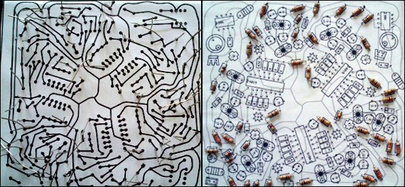
1- print the sche­ma­tic you want (be sure to inclu­de on the she­et of paper both sides of the sche­ma­tic (com­po­nent side and schematic)

2‑fold it (the idea is to fold whe­re the com­po­nent side meets the schematic)

3‑cut a pie­ce of card­bo­ard and insert it in the mid­dle of the she­et of paper

4‑glue both sides on to the card­bo­ard (now you must have a beau­ti­full cir­cuit board made of cardboard)

5‑with a nee­dle pier­ce (com­po­nent side) all dril­ling holes into sche­ma­tic side

6‑insert the com­po­nents (resis­tors, ic, capa­ci­ta­tor etc..)

7‑turn it back (sche­ma­tic side) and start to sol­der (be sure to folow the tra­ces on the paper), the best way to do this is to sim­ply bend the leads of the com­po­nents and sol­der them together, if you have a lar­ge area were the lead is not long enough just use a wire or something similar.

8‑have fun