Drum Pads

drumpads1drumpads2

Hey.

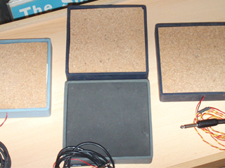
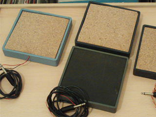
Four drum pads ready to go.

All made of old mate­ri­al found in the Alt/Lab ins­tal­la­ti­ons, and a very spe­ci­al big thankxxx for Móni­ca who brought the casings (we are going back to that in a moment) for the drum pads.

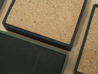
So the idea was to make drum pads that we could hook up to a sound card(or wha­te­ver) and them make swe­et music, this is a very nice com­bi­na­ti­on betwe­en pie­zo­e­lec­tric com­po­nents and a few layers of some absor­bent sound  mate­ri­al like rub­ber or cork foil (that’s what we use becau­se the­re was nothing more) and a pie­ce of alu­mi­num foil for a gre­a­ter drum area .

We use an old can (20l) of paint, four pie­zo­e­lec­tric found in elec­tro­nic junk like old modems and old telepho­nes, wire for con­nec­ting the pie­zos, cork foil for insu­la­ti­on the drum pad area and Móni­ca sup­ply the casings (squa­re rub­ber cd´s stands), and glue for put­ting everything nice and tight .

First we cut a pie­ce of the can (cir­cu­lar about 10cm radius)and we glu­ed the pie­zo into it, then we dril­led one hole into the rub­ber casing for the wires to came out, them we cut two squa­re cork foil parts (the first in the bot­tom of the casing and the other for the top) a bit of glue and that’s it drum pads ready to rock.

Now we got some audio coming out of the pads but thats just boring becau­se its always the same and we want to go further like trans­for­ming audio into midi mes­sa­ges, and we found the right tool for it, its cal­led  “KTDrum­Trig­ger” and he trans­forms the audio sig­nal into midi notes, we can use this midi notes insi­de a sequen­cer pro­gram to con­trol any kind of ins­tru­ment (either VSTI or some other stuff), in our case we use the drum pads to con­trol “Bat­tery” and thats it ins­tant fun.

The­re are some other links and some other ide­as for drum pads. This “one“uses ardu­nio as a sour­ce for the imput signal.

drumpads3

Circuit Bending

Hel­lo “intre­nets” people(s)

This post today reflects a lit­tle about  what cir­cuit ben­ding and diy are.

I have many fri­ends and col­le­a­gues  asking me “-So what is cir­cuit ben­ding?”, well here goes the awser and a bit of the his­tory behind cir­cuit bending.

Seems that a guy cal­led Reed Gha­za­la, was making expe­ri­ments with some synthe­si­zers, trying to get some more sounds out of the elec­tro­nic ins­tru­ments, so he deci­ded to open one and poke the guts of the beast .

He soon  finds out that the core of an elec­tro­nic ins­tru­ment its a lot of fun and this could be exci­ting discover.

Now…have you ever heard of the Savant syn­dro­me ?  a per­son who as Savant Syn­dro­me have the abi­lity of mixing emo­ti­ons, like seeing num­bers in a wide vari­ety of colors or the alpha­bet in sha­pes and forms, the cau­se of this, its sim­ply the brain and some short fuses in some are­as, and this its exac­tly what Cir­cuit ben­ding is.

So, when Reed deci­ded to explo­re the pos­si­bi­lity of the short cir­cuit he open a big door for expe­ri­men­tal music and a new form of seeing elec­tro­nic devi­ces, the idea its sim­ply bril­li­ant, lets open some toys, synths, pedals (wha­te­ver) and lets start to take some really cool sounds out of it, and the bril­li­ant part is : you don’t need to know about elec­tro­nics or be a geek who spent all day in the gara­ge (myself inclu­ded), becau­se cir­cuit ben­ding its like a a brain in short fuse.

What you need to cir­cuit ben­ding some stuff ?  This is another ques­ti­on and an impor­tant one. Hummm lets see:

First, you will need some kind of devi­ce that pro­du­ces sound, like a toy, a dis­tor­ti­on pedal, an old synth just to name a few.

Second, this is the impor­tant part DON’T USE ANYTHING THAT CONNECTS DIRECTLY TO THE AC/DC POWER, this means DEATH, ins­te­ad use bat­te­ri­es, all kinds of bat­te­ri­es and even trans­for­mers as long you don’t tou­ch that evil 220 V you are in business .

Third, open your devi­ce and cho­o­se your method of ope­ra­ti­on, this could be done in a vari­ety of ways, you could use your fin­gers with a lit­tle of sali­va (ughhh), or two screw dri­vers con­nec­ted by an alli­ga­tor clip.

Four, explo­re and see if the devi­ce reacts to your tou­ch poking some cir­cuits, i often get some gre­at results poking the chips legs and con­nec­ting them together, fin­ding the cool points its fun so don’t give up if you don’t find something in the first 5 minutes.

Five, ohh the “intre­nets” yes the­re’s a lot in here just sear­ch a bit and you will find your­self in a brand new world, of cour­se the cir­cuit ben­ding com­mu­nity its open min­ded and fri­en­dly, so don’t be shy and ask ques­ti­ons (most of us don’t know what are doing so join the club).

Now you know were Beck, Madon­na, Mike Pat­ton and many others are get­ting they ins­pi­ra­ti­on (yeah that’s right Madon­na), the musi­cal pos­si­bi­lity are immen­se, just think  is you, who  are dis­co­ve­ring your own sounds and making it at the same time (not like a pat­ch in a synthe­si­zer ) something really new and fresh made enti­rely  by you.

So,  what is Cir­cuit Bending ?

Paper and cardboard circuits

papercircuits_01
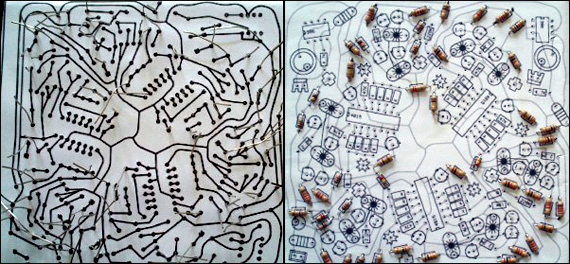
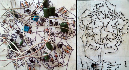
A cou­ple of years ago i found out on the “inter­nets” that you don’t really need a pro­to­bo­ard or a cir­cuit board to make your cir­cuits come to life, the idea was to fold a pie­ce of paper with the cir­cuit design in it (com­po­nent side and cir­cuit dia­gram side) and then inser­ting a pie­ce of card­bo­ard in the middle.

The main idea was the eco, recy­cled “thingy” sin­ce cir­cuit boards are not so eco fri­en­dly and take a bun­ch of time to get recy­cled by our mother earth, also the eco­no­mic side (paper and card­bo­ard are almost free), ins­te­ad cir­cuit boar­ding takes a long time and it’s hazar­dous for the environment.

papercircuits_02
So here’s what i do :

1- print the sche­ma­tic you want (be sure to inclu­de on the she­et of paper both sides of the sche­ma­tic (com­po­nent side and schematic)

2‑fold it (the idea is to fold whe­re the com­po­nent side meets the schematic)

3‑cut a pie­ce of card­bo­ard and insert it in the mid­dle of the she­et of paper

4‑glue both sides on to the card­bo­ard (now you must have a beau­ti­full cir­cuit board made of cardboard)

5‑with a nee­dle pier­ce (com­po­nent side) all dril­ling holes into sche­ma­tic side

6‑insert the com­po­nents (resis­tors, ic, capa­ci­ta­tor etc..)

7‑turn it back (sche­ma­tic side) and start to sol­der (be sure to folow the tra­ces on the paper), the best way to do this is to sim­ply bend the leads of the com­po­nents and sol­der them together, if you have a lar­ge area were the lead is not long enough just use a wire or something similar.

8‑have fun