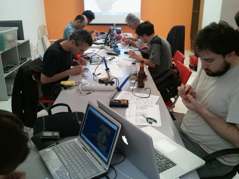
Terrific night yesterday @ altlab!
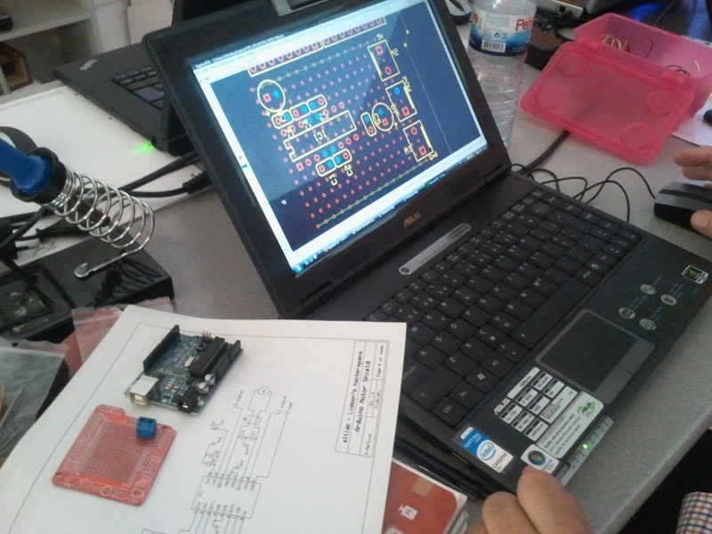
The workshop started with an intro to electronics leaving the attendees anxious to get down to soldering.
Despite that, everyone was focusing their attention on what was being said.
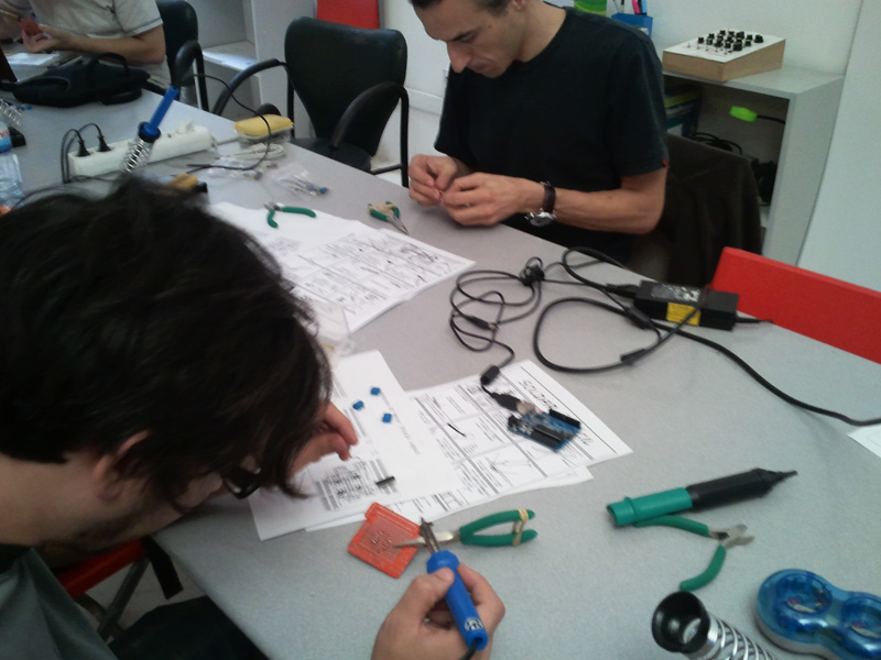
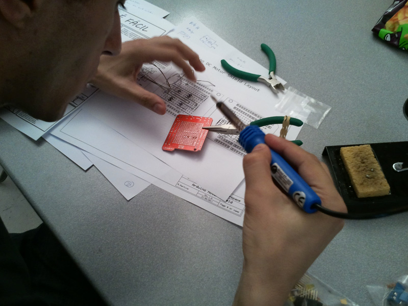
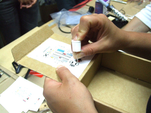
Half an hour later the soldering irons were plugged in and the fun started.

Hands-on and having fun!

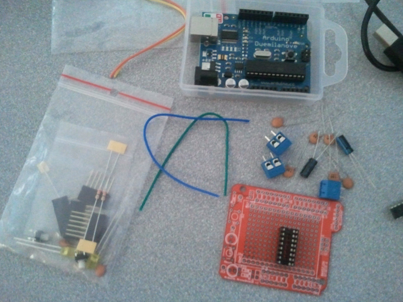
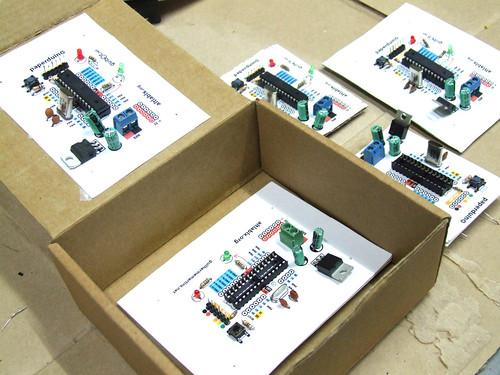
Blinking LED KIT

A new Hacker is born ! @Ricardo Castelhano
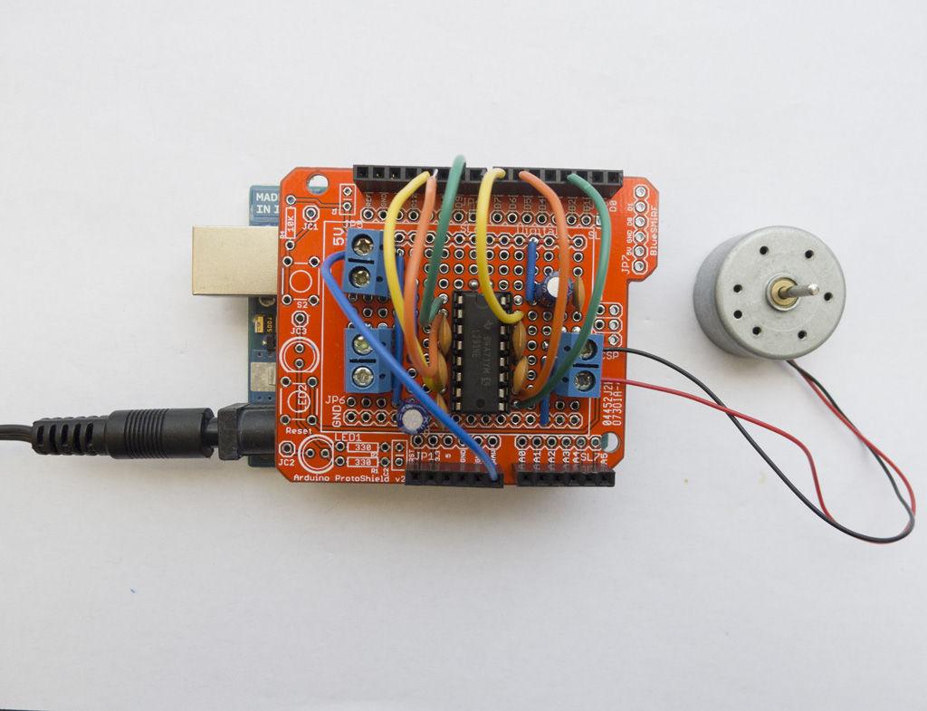
Here is the final result, everyone leaves with their own blinking gadget.
More photos @flickr
(scroll down for English)
 Vamos pegar aleatóriamente num motor de passo e tentar descobrir que tipo de motor é, desenhar um diagrama simples do mesmo.
Depois vamos pegar no ferro de soldar (não há que ter meeeeeedo :)) e montar um circuito que permite controlar esse motor a partir de um Arduino ou qualquer outra placa baseada num microcontrolador.
Todo o material é fornecido e fica para os participantes, sendo apenas necessário trazer ferro de soldar e multimetro (ou esperar que alguma alma caridosa vos empreste).
O número de participantes é limitado pelo que, se disserem que vêm, contamos MEEESMO convosco 😉
Para inscrições e pedidos de informação: workshops /arroba/ audienciazero.org
Lotação máxima de 10 participantes
Sábado 13 de Março de 2010
AltLab em Cacilhas
14h00m
5€
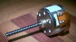
Let’s each of us pick up a random stepper and try to find out what kind of stepper it is, draw a simple diagram.
Then pick up the soldering iron (have noooooo fear :)) and assemble a circuit to control that motor from an Arduino or any other microcontroller-based board.
All materials are supplied to the participants and everyone gets to keep them; you’re just required to bring your own soldering iron and multimeter (or wait a random amount of time to borrow someone else’s).
The number of participations is limited, therefore, if you tell us you’ll come, we’ll REEEALLY be waiting for you 😉
For registration and information requests: workshops /at/ audienciazero.org
Maximum of 10 participants
Saturday, March 13 2010
AltLab @ Cacilhas
14h00m
5€
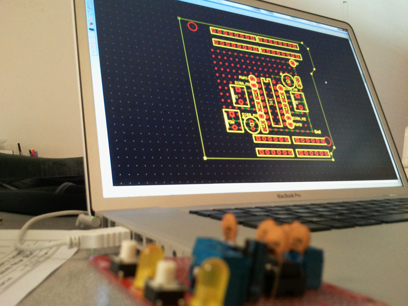
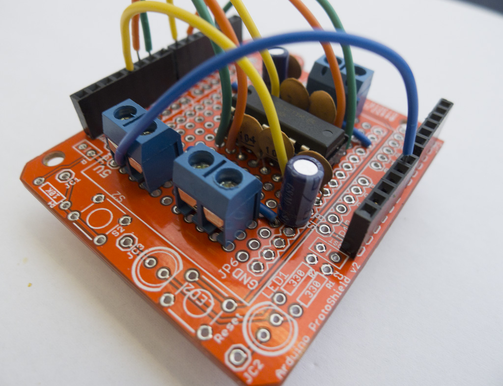
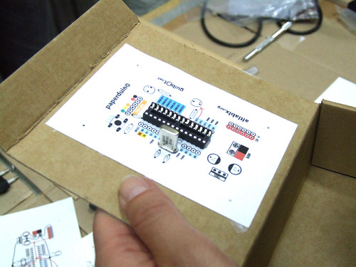
This is a fully functional version of the Arduino. We eliminated the PCB and use paper and cardboard as support and the result is.. the PAPERduino 😀
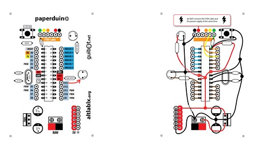
This is the the first version of the layout design, next we will try more designs, and other materials. You just need to print the top and the bottom layouts, and glue them to any kind of support you want. We hope that you start making your own boards. If you do, please share your photos with us, we would love to see them 😉
There is no USB direct connection, so to program the paperduino you will need some kind of FTDI cable or adapter. One of this products will be fine:
FTDI cable from Adafruit Industries
FTDI adapter from Sparkfun
Components list:
1 x 7805 Voltage regulator
2 x LEDs (different colors)
2 x 560 Ohm resistors (between 220oHm and 1K)
1 x 10k Ohm resistor
2 x 100 uF capacitors
1x 16 MHz clock crystal
2 x 22 pF capacitors
1 x 0.01 uF capacitor
1 x button
1 x Atmel ATMega168
1 x socket 28 pin
Female and Male headers

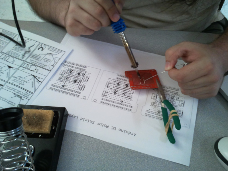
Instructions:
Use a needle to puncture the holes for your components.
Don’t rush, place one component after another and do all the solder work carefully.
Follow the connection lines.
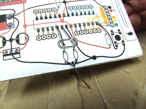
And this should be the final look of your paperduino connections.

![]()
My dear friend Kisty Boyle and I recently launched openMaterials — a collaborative research project dedicated to open investigation and experimentation with DIY production methods and uses of materials. In the spirit of the open source software and hardware movements, we hope to promote materials to be researched and developed in a public, collaborative manner. We see materials as an open resource, and wish to establish an open process for exploring and sharing knowledge, techniques and applications related to materials science.
I’ll be conducting most of my hands-on research right here at AltLab. We’d love for you to be involved if you are working in these areas or interested in learning more about smart materials.