Offf’09 rocked!

Offf’09 rocked!
Hello “intrenets” people(s)
This post today reflects a little about what circuit bending and diy are.
I have many friends and colleagues asking me “-So what is circuit bending?”, well here goes the awser and a bit of the history behind circuit bending.
Seems that a guy called Reed Ghazala, was making experiments with some synthesizers, trying to get some more sounds out of the electronic instruments, so he decided to open one and poke the guts of the beast .
He soon finds out that the core of an electronic instrument its a lot of fun and this could be exciting discover.
Now…have you ever heard of the Savant syndrome ? a person who as Savant Syndrome have the ability of mixing emotions, like seeing numbers in a wide variety of colors or the alphabet in shapes and forms, the cause of this, its simply the brain and some short fuses in some areas, and this its exactly what Circuit bending is.
So, when Reed decided to explore the possibility of the short circuit he open a big door for experimental music and a new form of seeing electronic devices, the idea its simply brilliant, lets open some toys, synths, pedals (whatever) and lets start to take some really cool sounds out of it, and the brilliant part is : you don’t need to know about electronics or be a geek who spent all day in the garage (myself included), because circuit bending its like a a brain in short fuse.
What you need to circuit bending some stuff ? This is another question and an important one. Hummm lets see:
First, you will need some kind of device that produces sound, like a toy, a distortion pedal, an old synth just to name a few.
Second, this is the important part DON’T USE ANYTHING THAT CONNECTS DIRECTLY TO THE AC/DC POWER, this means DEATH, instead use batteries, all kinds of batteries and even transformers as long you don’t touch that evil 220 V you are in business .
Third, open your device and choose your method of operation, this could be done in a variety of ways, you could use your fingers with a little of saliva (ughhh), or two screw drivers connected by an alligator clip.
Four, explore and see if the device reacts to your touch poking some circuits, i often get some great results poking the chips legs and connecting them together, finding the cool points its fun so don’t give up if you don’t find something in the first 5 minutes.
Five, ohh the “intrenets” yes there’s a lot in here just search a bit and you will find yourself in a brand new world, of course the circuit bending community its open minded and friendly, so don’t be shy and ask questions (most of us don’t know what are doing so join the club).
Now you know were Beck, Madonna, Mike Patton and many others are getting they inspiration (yeah that’s right Madonna), the musical possibility are immense, just think is you, who are discovering your own sounds and making it at the same time (not like a patch in a synthesizer ) something really new and fresh made entirely by you.
So, what is Circuit Bending ?
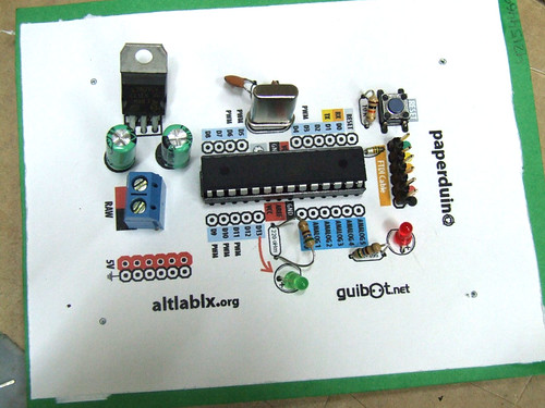
This is a fully functional version of the Arduino. We eliminated the PCB and use paper and cardboard as support and the result is.. the PAPERduino 😀
This is the the first version of the layout design, next we will try more designs, and other materials. You just need to print the top and the bottom layouts, and glue them to any kind of support you want. We hope that you start making your own boards. If you do, please share your photos with us, we would love to see them 😉
There is no USB direct connection, so to program the paperduino you will need some kind of FTDI cable or adapter. One of this products will be fine:
FTDI cable from Adafruit Industries
FTDI adapter from Sparkfun
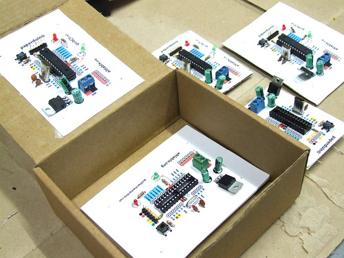
Components list:
1 x 7805 Voltage regulator
2 x LEDs (different colors)
2 x 560 Ohm resistors (between 220oHm and 1K)
1 x 10k Ohm resistor
2 x 100 uF capacitors
1x 16 MHz clock crystal
2 x 22 pF capacitors
1 x 0.01 uF capacitor
1 x button
1 x Atmel ATMega168
1 x socket 28 pin
Female and Male headers
Instructions:
Use a needle to puncture the holes for your components.
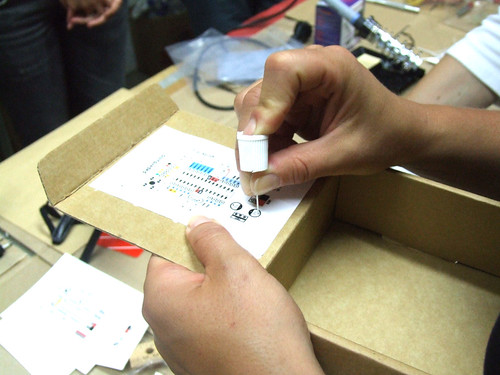
Don’t rush, place one component after another and do all the solder work carefully.
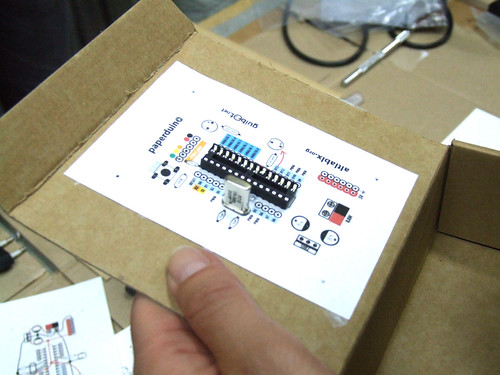
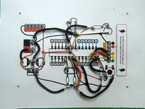
Follow the connection lines.
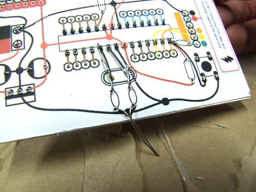
And this should be the final look of your paperduino connections.

We had a great time building this electronic/paper pieces, and more are to come pretty soon .)
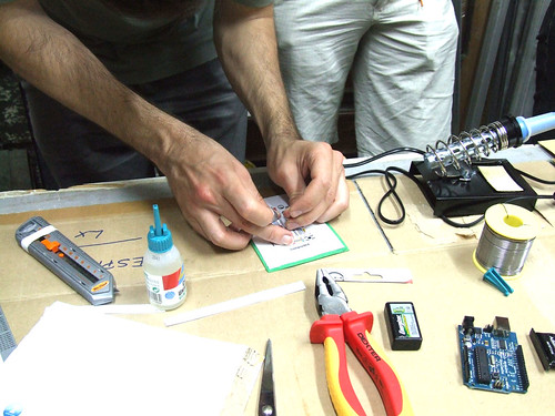
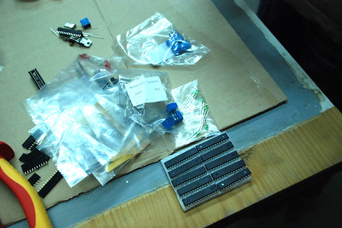
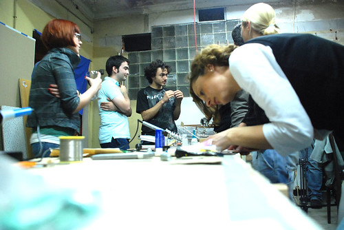
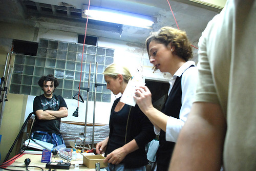
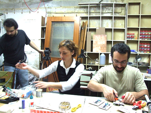
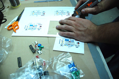
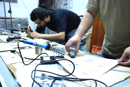
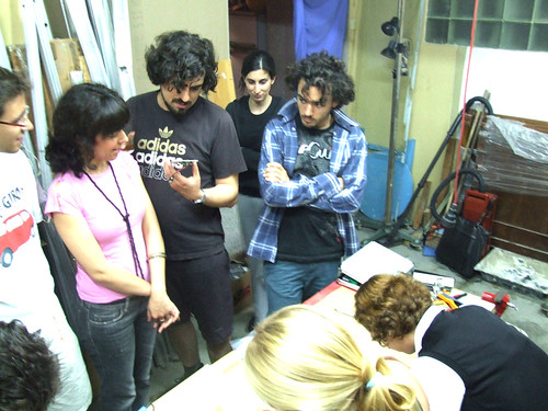
We are happy to introduce the paperduino 😀
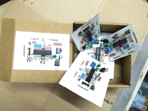
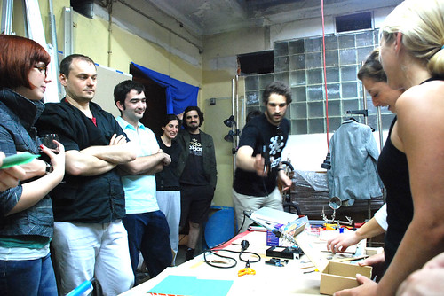
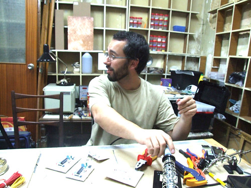
This Tuesday AltLab had its first public session and we did a mini workshop on “paperduinos”, a new generation of cardboard arduinos. We had lots of fun and have many more ideas we’d like to try: different layouts, colored papers, and other materials. More info soon.

