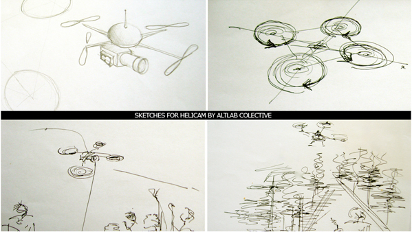
Project Helicam

Helicam Sketches

Heli­cam is an AltLab pro­ject that emer­ged from the wish to cap­tu­re ima­ges from the sky with a WiFi ena­bled came­ra so that one can see what’s being shot from a dif­fe­rent pers­pec­ti­ve and in real-time. This appro­a­ch may lead to new para­digms in visu­al pers­pec­ti­ves by ena­bling sho­o­ting from air views at a con­si­de­ra­bly low cost and also so clo­se that can­not be easily done from a helicopter.

As a real exam­ple, one of the pro­jects to accom­plish with Heli­cam is for tes­ting for local forests sur­veil­lan­ce and use in rela­ted rese­ar­ch pro­jects, as with forest fire pre­ven­ti­on for sus­tai­na­bi­lity. Other pos­si­ble ope­ra­ti­on fields can be archi­tec­tu­re, buil­ding sur­veil­lan­ce or even artis­tic per­for­man­ce envi­ron­ments whe­re mul­ti­me­dia has a strong presence.

The main idea is to build an inex­pen­si­ve and fle­xi­ble plat­form using – as a star­ting point – spe­ci­fi­ca­ti­ons made avai­la­ble by seve­ral open sour­ce pro­jects avai­la­ble onli­ne (like Mikro­kop­ter or UAVP-NG). After doing some ini­ti­al rese­ar­ch and costs eva­lu­a­ti­on we rea­li­zed that we can­not make this pro­toty­pe with the resour­ces cur­ren­tly avai­la­ble within the group mem­bers or AltLab and the­re­fo­re we star­ted to seek for some kind of spon­sorship. I have to say that we were lucky sin­ce with only two con­tacts made, we were able to fun­drai­se money in order to build a flying pro­toty­pe accor­ding to our ini­ti­al costs pre­dic­ti­ons. Thank you Mob­bit for accep­ting our proposal!!

If you wan­na join us in this pro­ject stop by AltLab in one of our regu­lar Tues­day night meetings.

Make your own game-pad!

…Don’t let others tell you how many but­tons you can press at once, the­se are times of freedom 🙂

This is a home­ma­de game-pad with just one acce­le­ro­me­ter (a bre­a­kout board from Spark­fun) and one push-button.

custom game-pad with accelerometer and push-button connected to arduino

Using a sim­ple, cus­tom pro­to­col and a C# lis­te­ner we could play Acce­le­roids, an Aste­roids lost sibling on Ste­roids, whi­ch uses the acce­le­ro­me­ter to con­trol the ship and the but­ton to shoot.

next steps will be to turn this into a gene­ric game-pad by simu­la­ting key­bo­ard key pres­ses for any sen­sor you throw at the Ardui­no, allowing you to cre­a­te truly funky pads to con­trol your favou­ri­te game. Stay tuned! 😉

Edit: We were aler­ted by fri­en­dly com­ments that this pro­ject resem­bles another project/tutorial that can be found here: http://lusorobotica.com/index.php/topic,902.0.html

PAPERduino’s design

This is a fully func­ti­o­nal ver­si­on of the Ardui­no. We eli­mi­na­ted the PCB and use paper and card­bo­ard as sup­port and the result is.. the PAPERduino 😀

This is the the first ver­si­on of the layout design, next we will try more designs, and other mate­ri­als. You just need to print the top and the bot­tom layouts, and glue them to any kind of sup­port you want. We hope that you start making your own boards. If you do, ple­a­se sha­re your pho­tos with us, we would love to see them 😉

The­re is no USB direct con­nec­ti­on, so to pro­gram the paper­dui­no you will need some kind of FTDI cable or adap­ter. One of this pro­ducts will be fine:
FTDI cable from Ada­fruit Industries
FTDI adap­ter from Sparkfun

Down­lo­ad PDF

Com­po­nents list:
1 x 7805 Vol­ta­ge regulator
2 x LEDs (dif­fe­rent colors)
2 x 560 Ohm resis­tors (betwe­en 220oHm and 1K)
1 x 10k Ohm resistor
2 x 100 uF capacitors
1x 16 MHz clock crystal
2 x 22 pF capacitors
1 x 0.01 uF capacitor
1 x button
1 x Atmel ATMega168
1 x soc­ket 28 pin
Fema­le and Male headers

Ins­truc­ti­ons:
Use a nee­dle to punc­tu­re the holes for your components.

Don’t rush, pla­ce one com­po­nent after another and do all the sol­der work carefully.

Fol­low the con­nec­ti­on lines.

And this should be the final look of your paper­dui­no connections.