
2015-06-30 - Nº 9
Editorial
Com a 9ª Newsletter completam-se nove semanas de novidades, artigos de interesse, circuitos, peças 3D, etc. Hoje o dia tem mais 1 segundo - o chamado "leap second". Este sistema implementado em 1972 já foi usado 25 vezes e serve para corrigir a velocidade da rotação da terra em relação ao chamado tempo atómico. Espero que seja usado para ler a Newsletter.
Esta Newsletter encontra-se mais uma vez disponível no sistema documenta do altLab. Todas as Newsletters encontram-se indexadas no link.
Esta Newsletter tem os seguintes tópicos:
- Novidades da Semana
- Ciência e Tecnologia
- Cursos MOOC
- Modelos 3D
- Open Source
- Circuitos
- Artigo do Maker
- Compras
Atendendo a que este mês somos presenteados com mais um segundo resolvi usar o tema dos relógios em varias das secções da Newsletter e temos um projeto de um Maker que implementa o Relógio de Berlim ou Mengenlehreuhr. Iremos falar de Charlieplexing nos Circuitos e é apresentada a melhor ferramenta Open Source para se fazer acesso remoto a servidores - o PuTTY. Esta semana não há ferramenta.
 João Alves ([email protected])
O conteúdo da Newsletter encontra-se sob a licença  Creative Commons Attribution-NonCommercial-ShareAlike 4.0 International License.
Novidades da Semana ^
Airbus to build satellites for OneWeb to beam Internet from space

"Europe's Airbus Group will design and build about 900 satellites for privately owned OneWeb Ltd, which plans to offer high-speed, space-based Internet access to billions of people worldwide, company officials said on Monday. About 700 of the satellites, each of which will weigh less than 330 pounds (150 kg), will be launched into orbit around Earth beginning in 2018. The rest will stay on the ground until replacements are needed, said OneWeb, based in Britain's Channel Islands."
-

"Autonomous vehicle technology is another step closer to production at Ford – moving from a research effort to an advanced engineering project. Ford announces it is working with Silicon Valley-based 3D-printing firm Carbon3D to quickly produce high-quality automotive-grade parts. Ford kicks off wearable technology development with MyFord® Mobile app extension – coming soon to smartwatches including Android Wear – providing customers the ability to check vehicle driving range, battery charge and more for their plug-in hybrid or electric vehicle quickly from their wrists"
Arduino and Seeedstudio announce partnership in Shenzhen
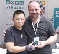
"Seeedstudio will manufacture and distribute Arduino LLC products using the new Genuino brand in China and other Asian markets. The new Genuino name certifies the authenticity of boards, in line with the open hardware and open source philosophy that has always characterized Arduino. Genuino is Arduino LLC new sister-brand created by co-founders Massimo Banzi, David Cuartielles, Tom Igoe and David Mellis for markets outside of the USA."
Ciência e Tecnologia ^
Leap Second on Tuesday Will Cause 61-Second Minute

"The transition from June to July will be delayed by circumstances beyond everyone's control. Time will stand still for one second on Saturday evening (June 30) because a "leap second" will be added to let a lagging Earth catch up to super-accurate clocks."
Robots to 3D print gravity-defying steel bridge in mid-air over Amsterdam canal

"An ornate steel bridge will be built in mid-air over a canal in Amsterdam in 2015 using 3D printing and robots, and surprisingly it will not require support structures. Dutch 3D printing R&D startup MX3D has invented a 3D printing technique whereby multi-axis industrial robots are able to print strong, complex structures anywhere without needing a print bed."
Flexible One Diode-One Phase Change Memory Array Enabled by Block Copolymer Self-Assembly
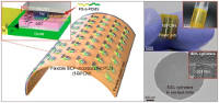
"Flexible memory is the fundamental component for data processing, storage, and radio frequency communication in flexible electronic systems. Among several emerging memory technologies, phase-change random-access memory (PRAM) is one of the strongest candidate for next-generation nonvolatile memories due to its remarkable merits of large cycling endurance, high speed, and excellent scalability. Although there are a few approaches for flexible phase-change memory (PCM), high reset current is the biggest obstacle for the practical operation of flexible PCM devices. In this paper, we report a flexible PCM realized by incorporating nanoinsulators derived from a Si-containing block copolymer (BCP) to significantly lower the operating current of the flexible memory formed on plastic substrate. The reduction of thermal stress by BCP nanostructures enables the reliable operation of flexible PCM devices integrated with ultrathin flexible diodes during more than 100 switching cycles and 1000 bending cycles."
Cursos MOOC ^
- Cracking Mechanics: Further Maths for Engineers - Começa a 6 de Julho
- An Introduction to Interactive Programming in Python (Part 2) - Começa a 11 de Julho.
- Introduction to Cyber Security - Começa a 13 de Julho
- Creative Coding - Começa a 3 de Agosto.
Modelos 3D ^
Com a disponibilidade de ferramentas que permitem dar azo a nossa imaginação na criação de peças 3D e espaços como o thingiverse para as publicar, esta rubrica apresenta alguns modelos selecionados que poderão ser úteis.
Clock Builder Script (http://www.thingiverse.com/thing:8271)
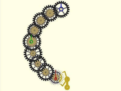
There are things that get re-used by various clocks and test jigs, but don't really merit inclusion in the library itself. I got a little tired of managing multiple clock scripts, and having to make sure the latest improvements made it into the various configurations.
So, all this common logic, for placing the gears, making them mesh and rotate, or laying them out to print, etc... that's all now contained in this clock builder script which calls MCAD for the gears and my clockwork library for the clockwork.
It, in turn is called by short scripts that contain only the parameter values for a particular clock, and any clock-specific code you might care to add (like a frame design, since I haven't come up with a good generic one yet).
Which means that if you want to play with clock configurations with as little as two or as many as nine wheels, with all, any or none of them bearing hands and/or concentric shafts, curled up as loose or as tight as you want, all you need to do is create a copy of a clock-script, and modify parameters to your heart's content. The core code and parameters are unchanged.
Seal embosser - Slap Chop (http://www.thingiverse.com/thing:797492)

Table Sun clock (http://www.thingiverse.com/thing:282793)
Once in a museum saw a simple clock device, had to had it. This is my render of it, trying it out in 3d application seems to work with different time of day. Needs real-life testing
C51 4 Bits Digital Electronic Clock Desk Case / Stand (http://www.thingiverse.com/thing:651175)
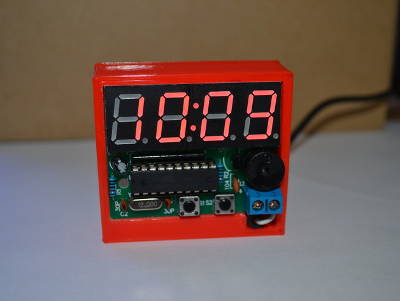
Desk stand for the popular C51 4 Bits Digital DIY Electronic Clock. Designed to be a tight fit such that the clock PCB can be inserted on an angle to maximise viewing while sitting on a desk.
Open Source ^
PuTTY

O PuTTY é a ferramenta Open Source mais utilizada para acesso a servidores. Implementa os protocolos SSH, Telnet e Rlogin.
Foi criada por Simon Tatham e é ativamente mantida por uma pequena equipa. Tendo inicialmente sido criada para Windows existe atualmente uma versão também para sistemas Unix. Encontra-se atualmente na versão beta 0.64. O software pode ser descarregado neste link.
O PuTTY tem as seguintes funcionalidades:
- Acesso a servidores usando Secure Shell (SSH-1 e SSH-2)
- Acesso a servidores usando Telnet
- Acesso a servidores usando RLogin
- Emulação de terminais xterm, VT102,
- Permite acesso RAW (Sem interpretação de protocolo)
- Cópia de ficheiros via SSH em linha de comando
- Cópia de ficheiros via SFTP em linha de comando
- Suporte de redireção dinâmico de portas (Incluindo X11)
- Suporte de IPv6
- Acesso a portas Série locais - COM
- Definição de velocidade, Bits de Dados, bits de Stop, Paridade e controlo de Fluxo na porta Série
- Permite gravar a sessão para ficheiro
- Permite gravar a configuração de sessão
- Pequena dimensão (512K) e transportável
Trata-se de uma simples mas completa ferramenta de acesso remoto.
Não tendo uma forma simples de gerir as sessões existem ferramentas como o WinSCP que permite ajudar nessa gestão.
Para terminar e por não parecer intuitivo para se aceder às configurações depois de estabelecida uma sessão deverá usar-se o botão da direita do rato no topo da janela. Desta forma é exposto o menu que tem inúmeras opções.
Links úteis:
- WinSCP - Integration with PuTTY
- 10 Awesome PuTTY Tips and Tricks You Probably Didn’t Know
- 10 things you probably wouldn’t have tried in PuTTY ?
- Improving Putty settings on Windows
Circuitos ^
Aqui é apresentado um circuito simples que poderá ser construído com componentes.
Charlieplexing
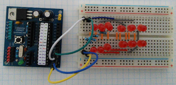
O circuito de hoje tem por objectivo podermos controlar bastantes LEDs com poucos pinos e sem recorrer a outros integrados. A técnica usada chama-se charlieplexing e foi proposto em 1994 por Charlie Allen da Maxim, tendo no entanto sido alvo de uma patente nos final dos anos 70 por parte da AEG-Telefunken.
A técnica usada por este método reduz o numero de pinos necessários para acender os LEDs pois os pinos assumem os três estados possíveis: alto, baixo e input (alta impedância ou desconectado). Para se controlarem n(n-1) LEDs são necessários n pinos ou de outra forma para se controlarem L LEDs são necessários (1+sqrt(1+4L))/2.
| Pins | LEDs |
|---|---|
| 1 | 0 |
| 2 | 2 |
| 3 | 6 |
| 4 | 12 |
| 5 | 20 |
| 6 | 30 |
| 7 | 42 |
| 8 | 56 |
| 9 | 72 |
| 10 | 90 |
| n | n²-n |
É preciso ter em atenção que este método recorre à propriedade da persistência de visão para que tenhamos a aparência de que estão vários LEDs acesos quando na pratica apenas está um. Para que essa aparência seja mantida é necessário que o refrescamento ocorra a mais de 50 Hz.
Por outro lado no circuito apresentado parte-se do principio que todos os LEDs são idênticos. Com LEDs diferentes torna-se necessário garantir que a "forward-voltage" dos LEDs é mais ou menos a mesma.
Esquemático
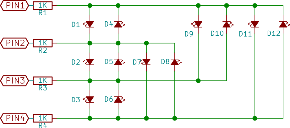
Nota: O circuito para o CSEduino pode ser consultado no Artigo do Maker da Newsletter Nº5. Pode igualmente ser usado um Arduino.
Componentes (BOM):
- 12x LED 5mm ou de 5mm (D1-D12)
- 4x Resistências de 1K Ohms (R1-R4)
Código
O Sketch usado foi o seguinte:
#include "Chaplex.h"

byte ctrlpins[] = {10,11,12,13};    //Arduino pins controlling charlieplexed leds
#define PINS 4                //number of these pins

#define DELAY 500             //speed of switching leds in bar on and off

Chaplex myCharlie(ctrlpins, PINS);     //control instance

charlieLed myLeds[]  = {
  { 0 , 1 },
  { 0 , 2 },
  { 0 , 3 },
  { 1 , 0 },
  { 1 , 2 },
  { 1 , 3 },
  { 2 , 0 },
  { 2 , 1 },
  { 2 , 3 },
  { 3 , 0 },
  { 3 , 1 },
  { 3 , 2 }
};

byte timer2TCNT2 = 178;    //preload timer 256-16MHz/1024/78 = near 5 ms

void setup() {
  // initialize timer2
  noInterrupts();                 //disable all interrupts
  TCCR2A = 0;
  TCCR2B = 0;
  TCNT2 = timer2TCNT2;
  TCCR2B |= (1 << CS22) | (1 << CS21) | (1 << CS20);  //prescaler 1024 = 64 micro secs
  TIMSK2 |= (1 << TOIE2);        //enable timer overflow interrupt
  interrupts();                  //enable all interrupts
}

ISR(TIMER2_OVF_vect) {          //timer2 interrupt routine
  myCharlie.outRow();           //output for one led row
  TCNT2 = timer2TCNT2;          //preload timer for next interrupt
}

void loop() {
  for (int i=0; i< PINS*PINS-PINS; i++) {
    myCharlie.ledWrite(myLeds[i], ON);
    delay(DELAY);
  }
  for (int i=0; i<PINS*PINS-PINS; i++) {
    myCharlie.ledWrite(myLeds[i], OFF);
    delay(DELAY);
  }
}
O Sketch faz uso de uma biblioteca que pode ser descarregada neste link ou então localmente daqui
Links úteis:
- Charlieplexing From Wikipedia, the free encyclopedia
- Charlieplexing - Reduced Pin-Count LED Display Multiplexing
- Charlieplexing LEDs- The theory
- What is Chaplex
- Charlieplexing LEDs with an AVR ATmega328 (or Arduino)
Artigo do Maker ^
Projeto interessante publicado por um maker.
Berlin Clock
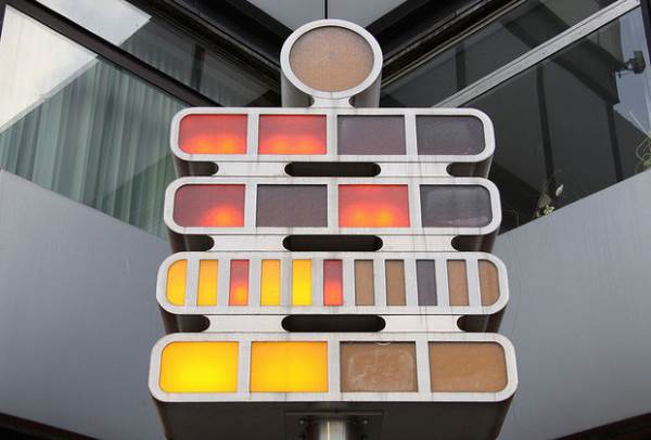
O Relógio de Berlim ou BerlinUhr ou Mengenlehreuhr é provavelmente o primeiro relógio digital. Foi instalado em Berlim em 1975. O Maker Mark de Loor apresenta neste link a sua implementação deste relógio.
A teoria por detrás do relógio é simples. Existem quatro linhas com luzes. A 1ª linha apresenta a hora multiplicada por 5. A seguinte apresenta de 1 a 4 (somar com a 1ª). A Terceira linha apresenta os minutos multiplicados por 5. A ultima linha apresenta os restantes minutos (a somar com a 3ª linha).
Na fotografia apresentada, (uma lâmpada encontra-se estragada...) a hora é: 2x5 horas mais 3 horas + 6x5 minutos + 2 minutos.
Portanto a hora é 13:32.
A lâmpada redonda no topo pisca a cada segundo.
Passo 1 - Alguma electrónica
O que é preciso para o projeto:
- Um Arduino
- Um RTC - Real Time Clock - Baseado no DS 1307.
- 13 LEDs amarelos de 5mm
- 11 LEDs Vermelhos de 5mm
- 1 Protoboard
- 1 Resistência de 220 Ohms
- 1 Resistência de 68K Ohms
- 1 MAX7219
Foi usada a biblioteca LedControl - que pode ser descarregada aqui
Passo 2 - Preparando a coisa
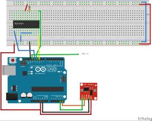
O datasheet do 7219 pode ser descarregado daqui.
Foram usados os pinos SDA e SCL para usar o RTC e mais quatro outputs: DataIn, Clock e ChipSelect que vão para o MAX7219 e o Pino 13 que foi usado para o piscar dos segundos.
O Arduino faz a maior parte do trabalho: lê o relógio, converte para as diferentes tipos de saídas e envia os dados para o MAX7219.
Vamos resumir os pinos do 7219: Pinos 4 e 9 ligados ao GND Pino 19 ligado ao VCC Pino 18 é o ISet ligado ao VCC com uma resistência. Deverá usar-se a resistência de 68K. Pino 1 é o DataIn que vem do pino 12 do Arduino Pino 12 é o Load que vem do pino 10 do Arduino Pino 13 é o Clk que vem do pino 11 do Arduino
Isto são os inputs.
Para os outputs:
O IC 7219 tem a possibilidade de ligar 8 displays de 7 segmentos. Estes outputs, DIG0 até DIG4 são usados para ligar às "linhas" dos LEDs: como a linha dos "cinco-minutos" tem 11 LEDs, foi usado o DIG1 e o DIG2 para tratar delas.
Os outros outputs: Segmentos A a G e DP (de um display de 7 Segmentos normal).
Neste caso com a biblioteca LedControl serão enviados valores binários.
Passo 3 - Os LEDs
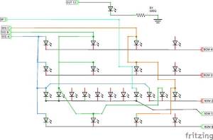
Neste esquemático, é possível ver como os LEDs estão ligado entre si. Apenas estão desenhadas os primeiros 3. Os outros são da mesma forma.
O LED dos segundos está ligado diretamente ao pino 13 do Arduino.
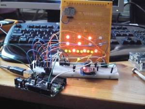
A fotografia mostra "como funciona". O relógio marca 17:47.
Passo 4 - O Código
#include <LedControl.h>
#include <Wire.h>

const int DS1307 = 0x68;

// A5 =SCL, A4 =SDA

const char* days[] = {"Sunday", "Monday", "Tuesday", "Wednesday", "Thursday", "Friday", "Saturday"};

const char* months[] = {"January", "February", "March", "April", "May", "June", "July", "August", "September", "October", "November", "December"};

byte second = 0; byte minute = 0; byte hour = 0; byte weekday = 0;
byte monthday = 0;
byte month = 0;
byte year = 0;
byte lastMinute = 0;
byte lastSecond =0;

int Led =13;

byte nul = B0000000;
byte een =B01000000;
byte twee = B01100000;
byte drie = B01110000;
byte vier = B01111000;
byte vijf = B01111100;
byte zes = B01111110;
byte zeven = B01111111;
byte acht = B11111111;
byte negen = B01000000;
byte tien = B01100000;
byte elf = B01110000;

int a=0; int b =0; int c =0;
int vijfMinTwee=0;

int uitgang = LOW;

/*pin 12 is connected to the DataIn pin 11 is connected to the CLK pin 10 is connected to LOAD */

LedControl lc= LedControl(12,11,10,1);

unsigned long delaytime=100;

void setup() {
  Wire.begin(); Serial.begin(9600);
  pinMode (Led, OUTPUT);
  lc.shutdown(0,false);
  /* Set the brightness to a medium values */
  lc.setIntensity(0,8);
  /* and clear the display */
  lc.clearDisplay(0);
}

void loop() {
  readTime();
  digitalWrite(Led,uitgang);
  if (second != lastSecond){
    if (uitgang == LOW) uitgang =HIGH;
    else uitgang =LOW;
    digitalWrite (Led, uitgang);
    lastSecond = second;
  }
  if (minute != lastMinute) { printTime(); lastMinute = minute;
  }
}

byte bcdToDec(byte val) {
  return ((val/16*10) + (val%16));
}

void printTime() {
  char buffer[3];

  long minuten = minute;
  long uren = hour;
  int vijfmin =minuten /5;
  int eenminuut = minuten -(vijfmin * 5);
  int vijfuren = uren/5;
  int eenuren = uren - (vijfuren *5);
  a = vijfmin;
  digitaal();
  vijfmin = b;
  vijfMinTwee = c;
  a = eenminuut;
  digitaal();
  eenminuut = b;
  a = vijfuren;
  digitaal();
  vijfuren = b;
  a = eenuren;
  digitaal();
  eenuren = b;
  lc.setRow(0,4,vijfuren);
  lc.setRow(0,3,eenuren);
  lc.setRow(0,1,vijfmin);
  lc.setRow(0,2,vijfMinTwee);
  lc.setRow(0,0,eenminuut);
}

void readTime() {
  Wire.beginTransmission(DS1307);
  Wire.write(byte(0));
  Wire.endTransmission();
  Wire.requestFrom(DS1307, 7);
  second = bcdToDec(Wire.read());
  minute = bcdToDec(Wire.read());
  hour = bcdToDec(Wire.read());
  weekday = bcdToDec(Wire.read());
  monthday = bcdToDec(Wire.read());
  month = bcdToDec(Wire.read());
  year = bcdToDec(Wire.read());
}

void digitaal(){
  switch (a){
  case 0:
    b= nul; c = nul;
    break;
  case 1:
    b = een; c = nul;
    break;
  case 2:
    b = twee; c = nul;
    break;
  case 3:
    b = drie; c = nul;
    break;
  case 4:
    b = vier; c = nul;
    break;
  case 5:
    b = vijf; c = nul;
    break;
  case 6:
    b = zes; c = nul;
    break;
  case 7:
    b = zeven; c = nul;
    break;
  case 8:
    b = acht; c = nul;
    break;
  case 9:
    b = acht; c = negen;
    break;
  case 10:
    b = acht; c = tien;
    break;
  case 11:
    b = acht; c = elf;
    break;
  }
}
O código deve funcionar sem problemas.
Resultado final
Outros projetos interessantes relacionados com relógios:
- The Fibonacci Clock
- LED Binary Clock
- Pong Clock
- The Word Clock - Arduino version
- Full Binary Clock
- Hellschreiber Clock
- Mini 7-Segment Clock V3
Compras ^
Artigos do ebay ou de outras lojas online que poderão ser úteis em projetos.
RTC I2C DS1307 AT24C32 Real Time Clock Module For Arduino AVR ARM PIC 51 ARM HC
(http://www.ebay.co.uk/itm/261592575984) - £0.99
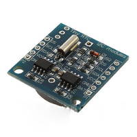
This module is without battery(battery type is LIR2032) ,because we received the notice from the post office that they don\'t accecpt goods with batteries.Therefore,please buy cautiously.
This is the DS1307 Real Time Clock developed by one of our designer waiman. The module comes fully assembled and pre-programmed with the current time (ok, so it\'s our current time - MST). The DS1307 is accessed via the I2C protocol.
- Two wire I2C interface
- Hour : Minutes : Seconds AM/PM
- Day Month, Date - Year
- Size: 28x25x10mm
- Leap year compensation
- Accurate calendar up to year 2100
- 1Hz output pin
- 56 Bytes of Non-volatile memory available to user
Package include:
- 1x DS1307 Module
DIY DS3231 Precision RTC Clock Memory Module for Arduino Raspberry Pi
(http://www.ebay.co.uk/itm/321740558651) - US $1.72
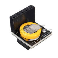
Overview:
Raspberry Pi DS3231 foreign high precision clock module
Pay attention to the module Arduino motherboard can also be used.
The module itself can be adapted to 3.3 V and 5 V system, no level conversion, it is super convenient!
Features:
- to 40ºC to + 85ºC temperature range, timing accuracy in a plus or minus 5 PPM (+/- 0.432 SEC/day)
- To provide continuous timing battery backup
- Low power consumption
- The device compatible with DS3231 encapsulation and function
- Complete the clock calendar function including the second, minute, time, week, date, month, and year, and provide the valid until 2100 leap year
- Two calendar clock
- 1 Hz and 32.768 kHz output
- Reset the output and input button to tremble
- High speed (400 KHZ) the I2C serial bus
- +2.3 V to +5.5 V power supply voltage
- The accuracy of plus or minus 3ºC digital temperature sensor
- -40ºC to +85ºC temperature range
Package included:
- 1 x DIY DS3231 Precision RTC Clock Memory Module for Arduino Raspberry Pi
New C51 4 Bits Digital Electronic Clock Electronic Production Suite DIY Kits FT
(http://www.ebay.co.uk/itm/321693158526) - £1.66
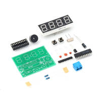
Features:
- AT89C2051-based of four electronic clock kit
- Kit Model: YSZ-4
- Supply voltage: 3V-6V
- PCB Size: 52mm * wide 42mm
Function:
- Seconds correction (for precise School)
- Switch to every minute independent display interface
- whole point of time (8-20 o\'clock chime can be turned off)
- Two alarm settings (you can turn off the alarm function)
Kit Features:
- 0.56 inch special red digital clock for display;
- Import AT89C2051 for master chip;
- 1.2mm thick PCB made from military grade FR-4 board;
- accurate travel time, travel time error range error -1 to +1 seconds every 24 hours.
Package included:
- 100% Brand New
- 1x Electronic Clock DIY Kits
- 1x Manual
NOTE: This produce is DIY kits, not the end product! We don\'t provide technical assistance please make sure you are familiar with the product before purchasing.
That's all Folks!